
Composite Sandwich Panel Analysis
Deflection, buckling and failure mode checks for sandwich panels with composite facesheets and a foam, honeycomb, or balsa core.
A composite sandwich panel is two thin, stiff composite facesheets bonded to a thick, lightweight core, which gives high bending stiffness at very low weight. The Sandwich Panel tool runs the same solve as the plate tool, with the rectangular plate built from two facesheets and a core. Each edge can be free, simply supported or clamped. The panel takes a uniform pressure, a patch load, or both, and buckling takes any mix of Nx, Ny and Nxy. On top of that solve the tool checks the failure modes that only exist once a core is involved1.
A sandwich panel works on the same principle as an I-beam. Bending stiffness grows with the square of the distance between the load-carrying flanges while facesheet thickness only counts linearly, so pushing two thin facesheets apart with something light buys more stiffness per gram than thickening either face. The facesheets carry the bending load as tension and compression; the core's job is to hold them apart and to transfer shear between them. That division of labour is what makes core properties matter in a way a solid laminate's do not.
When to use this tool
Use the sandwich construction when a solid laminate would need to get thick, and therefore heavy, to meet a deflection or buckling requirement: hulls and decks, floor and bulkhead panels, fairings, wind turbine shells, and any wide flat panel loaded in bending or in-plane compression. It answers two questions at once: how much the panel deflects or at what load it buckles, and which failure mode governs the design.
The facesheet stiffness comes from Classical Lamination Theory. When the facesheet laminate carries strength data, the tool also checks facesheet first ply failure (Maximum Stress criterion); for a full criterion comparison, run the First Ply Failure tool alongside it. Plate geometry, edges and loading are shared between the two constructions, so you can switch a panel from solid to sandwich and compare.
For a sandwich strip spanning between supports, such as a stiffener, a floor beam or a three-point bend coupon, use the Sandwich section of the beam tool instead. Both pages read the same facesheet laminate, mirror switch and core, so moving between them keeps the same sandwich.
Inputs
- Facesheet laminate sets both faces; the same laminate is used top and bottom. With "Bottom facesheet mirrors the top" on, the bottom face's stacking order is reversed, which keeps the panel symmetric about the core mid-plane even when the facesheet laminate itself is unsymmetric.
- Core: pick one from your library or enter the values directly. Core thickness (c), ribbon direction, shear modulus in the ribbon direction (Gc,L) and compressive modulus (Ec) are required. Show optional properties opens the transverse shear modulus (Gc,W), the shear strengths (Fsu,L, Fsu,W) and the compressive strength (Fcu). A blank transverse value takes the ribbon value. Save as new core stores what you typed in the core library.
- Plate geometry, edges and loading are the plate tool's own: length (a), width (b), an edge condition per side, and pressure, patch load or in-plane loads.
There is no D-matrix option in sandwich. Bending stiffness comes from the facesheets about the core mid-plane, and transverse shear stiffness from the core.
Results
- Response opens with the governing sandwich check and its safety factor, next to the maximum deflection or the buckling safety factor. Below that is the panel areal weight in g/m²: both facesheets plus the core, per unit area. It shows when every lamina in the facesheet and the core carry a density.
- Deflection or buckling load with a rigid core. Each result is shown next to the same panel with a core that does not deform in shear, and the difference in %. That gap is the core's shear flexibility: a large one says a stiffer or thicker core will help more than heavier facesheets.
- The Checks tab gives a safety factor per failure mode, with the governing mode and its safety factor highlighted. The facesheet stress check runs per ply (Maximum Stress criterion) and needs strength properties (S1t, S1c, S2t, S2c, S12) on every facesheet ply. Without them the stress is reported with no safety factor.
- ABD and Constants describe the two facesheets about the core mid-plane, the stiffness the plate is solved with. The core adds no in-plane stiffness, and the engineering constants are smeared over the full panel thickness, core included.
- Plot maps the panel over the plate in 2D or 3D. A Part select chooses what you see: the Panel shows w, M and Q; the Top and Bottom facesheet show Nx, Ny and Nxy, the moment carried as a force over the facesheet separation d (N = ±M/d); the Core shows Qx, Qy and the core shear stresses τxz = Qx/d and τyz = Qy/d, and opens on the largest τxz, the value the core shear check reads. Only a facesheet can be sent to the laminate tools, at the point you pick; picking a facesheet also selects it on the Resultants tab.
- Resultants: a separate tab giving one facesheet's membrane force at a time, top or bottom, ready to send to the laminate analysis tools. Positive pressure puts the top facesheet in compression and the bottom in tension; an in-plane load is shared evenly between the two. No Q is sent, since the core carries the shear. Sending the mirrored bottom facesheet also loads its reversed stack into the layup builder, so ply numbering matches the physical facesheet. If the builder already holds a custom layup, the tool asks before replacing it. See Force & Moment Resultants.
The sandwich panel tool. The Response tab leads with the governing failure mode, the maximum deflection and the panel areal weight.
Stiffness and deflection
Two stiffnesses describe the panel: a bending stiffness carried by the facesheets acting about the panel mid-plane, and a transverse shear stiffness carried by the core. The panel is solved as a plate with transverse shear deformation4, so deflection under pressure includes both a bending part and a shear part, on any edges.
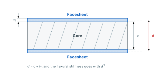
Every formula below uses the three dimensions above: the facesheet thickness tf, the core thickness c, and the distance d between the stiffness centroids of the two facesheets. For symmetric facesheets d = c + tf. A laminated facesheet carries its load closer to its stiffer plies, so with unsymmetric faces d differs by direction: dx for loads along x, dy for loads along y. Both are shorter when the stiff plies sit next to the core. The distance d runs between those centroids, not between the outer faces, so it is not the total panel thickness.
| Symbol | Name | Formula |
|---|---|---|
| Dpanel | Panel bending stiffness (thin faces) | |
| DQ,x, DQ,y | Transverse shear stiffness |
- Dpanel, panel bending stiffness: Bending stiffness per unit width (N·mm), from facesheet modulus Ef, facesheet thickness tf, and the distance d between the facesheet stiffness centroids. The d² term is the whole point of a sandwich: doubling the core thickness roughly quadruples the stiffness. The tool uses the full version of this: each facesheet's own ABD matrix moved to the panel mid-plane, so the faces' own bending stiffness and their bending-twisting coupling are kept. The core adds no in-plane stiffness.
- DQ,x, DQ,y, transverse shear stiffness: The core's resistance to shearing the facesheets past each other (N/mm), one per panel direction from the core shear modulus in that direction5. They set the shear deflection and cap the buckling load.
On a long, simply supported panel the result reduces to the familiar strip formulas, a bending deflection 5qb4/(384D) plus a shear deflection qb²/(8DQ) across the short span b. The two scale differently with span. Short, thick panels are shear dominated and long, thin ones bending dominated, which is why the tool reports the rigid core comparison.
With an unsymmetric facesheet laminate and the mirror off, the panel has membrane-bending coupling, and the tool uses the reduced bending stiffness D̃ = D − BA−1B. With the mirror on the coupling vanishes and D̃ = D.
Failure modes
A solid laminate fails one way: its plies break. A sandwich adds failure modes of its own, and the governing one is rarely obvious in advance, which is why the tool reports every mode with its own safety factor rather than a single number. General buckling is the plate result itself. The other modes are local and are checked on top of the plate solve.
| Symbol | Failure mode | Formula / allowable |
|---|---|---|
| σf | Facesheet stress | N = M/d per face, vs first ply failure |
| τxz, τyz | Core shear (x), (y) | Qx/d, Qy/d vs Fsu in that direction |
| σwr | Face wrinkling | |
| σcc | Core crushing | vs Fcu |
| λ | General buckling | The plate buckling result |
| Nx,cr, Ny,cr | Shear crimping (x), (y), (xy) |
- σf, facesheet stress: In-plane stress in the facesheets from the plate moments at the critical point, carried as a force couple over d. The safety factor is a per-ply Maximum Stress check. The faces are bonded to the core, so they cannot bend on their own. Each ply takes the strain of the whole panel at its own depth, so outer plies strain more than inner ones. The worse face governs.
- τxz, τyz, core shear: The largest transverse shear stress in the core in each direction, taken over the whole plate, edges included, since it peaks at the supports. Each is checked against the core's shear strength in that direction. Often the governing mode for foam cores under pressure loads.
- σwr, face wrinkling: Local instability of a compressed facesheet buckling into the core (MPa)6. It depends on the core's compressive modulus Ec, so a soft core lets the face wrinkle early. Ef and Gc are taken in the direction carrying the larger compression, and where that is not clear (pure shear, equal biaxial) the lower of each.
- σcc, core crushing: Through-thickness compression of the core from the pressure and the patch load, against its compressive strength. Also the mode that fails under clamps, fasteners, and bagging pressure with no bending load at all.
- λ, general buckling: The plate's buckling load factor, which already includes the core's shear flexibility for any edges and any combination of in-plane loads.
- Nx,cr, Ny,cr, shear crimping: A short-wavelength shear fold of the core. Nx is checked against Nx,cr, Ny against Ny,cr, and Nxy against the lower of the two. Reported as its own check so you can see when the core, not the facesheets, is capping the panel.
The buckling and crimping rows are two views of the same mechanism. A sandwich buckle shape shears the core, so a soft core lowers the buckling load; in the limit of a very soft core the buckling load levels off at the shear stiffness itself, and the buckle collapses into the short-wavelength crimp. Wrinkling and crimping waves are about as long as the core is thick, far too short for the plate solution to resolve, so both are checked in closed form.
The Checks tab. Each failure mode shows its load, its allowable and its safety factor, and the lowest safety factor governs.
Core materials
A core is described by far fewer numbers than a laminate, because it is not asked to do as much. Each property lines up with a specific failure mode from the list above:
| Property | Unit | What it governs |
|---|---|---|
| Gc,L, Gc,W, shear modulus (ribbon, transverse) | MPa | Shear deflection, the panel's shear stiffness, the core shear reduction of the buckling load, the shear crimping allowable and face wrinkling. The core's most important stiffness property |
| Ec, through-thickness compressive modulus | MPa | Face wrinkling resistance, since a soft core lets the facesheet buckle locally into it |
| Fsu,L, Fsu,W, shear strength (ribbon, transverse) | MPa | The core shear failure check in each direction |
| Fcu, compressive strength | MPa | Core crushing under pressure, and local crushing under fasteners or clamping |
| Density | g/cm³ | Panel areal weight. Nothing structural on its own, but it is the currency the others are bought with |
Foam and balsa are close to isotropic in shear, so a single shear modulus and strength describe them; leave the transverse values blank. Honeycomb is not. Its ribbon (L) direction, along the bonded double cell walls, is stiffer and stronger in shear than the transverse (W) direction, typically by roughly a factor of two2. Enter both and set the ribbon direction along the panel's x or y axis. Ribbon along x puts Gc,L in the xz plane and Gc,W in the yz plane; along y swaps them. Ribbon direction is disabled while both transverse values are blank, since an isotropic core has no ribbon direction.
The three families in common use trade off differently:
- Honeycomb (aluminium, or aramid paper such as Nomex) gives the best stiffness and strength for its weight, which is why it dominates aerospace. The cells are open, so it needs sealing at edges and around fasteners, and it is the least forgiving to process.
- Structural foam (PVC such as Divinycell, PET, PMI such as Rohacell) is closed-cell, easy to machine and shape, and takes a bonded joint anywhere on its surface. Weaker than honeycomb of the same density, and the cheapest to work with. The usual choice in marine and wind.
- Balsa is end-grain timber, so it is stiff and strong through the thickness at low cost. It absorbs resin and water, is variable as a natural material, and is heavier than a foam of comparable stiffness.
Within any one family, properties scale with density, so a core selection is largely a density selection.
The dashboard keeps cores in your material library alongside fibers, matrices, laminae and laminates, each with an optional source field so a datasheet or handbook value stays traceable. Presets for common Nomex, Rohacell, Divinycell and balsa grades are available to start from.
Cores live in the material library alongside fibers, matrices and laminates, with presets for common grades.
Author: Rick Schrijver
References
- Zenkert, D. (1995). An Introduction to Sandwich Construction. EMAS Publishing. ISBN: 978-0947817760. (Sandwich panel theory, wrinkling, and failure modes)
- US Department of Defense. (1968). Structural Sandwich Composites, MIL-HDBK-23A. (Core material properties, honeycomb and foam core design data, face wrinkling and core crushing)
- Barbero, E.J. (2018). Introduction to Composite Materials Design, 3rd ed. CRC Press. Chapter 10. (Sandwich panel design and core selection) doi:10.1201/9781315296494
- Reddy, J.N. (2003). Mechanics of Laminated Composite Plates and Shells: Theory and Analysis, 2nd ed. CRC Press. (First-order shear deformation plate theory)
- Allen, H.G. (1969). Analysis and Design of Structural Sandwich Panels. Pergamon. (Sandwich beams and plates with a shear-flexible core)
- Hoff, N.J., & Mautner, S.E. (1945). The buckling of sandwich-type panels. Journal of the Aeronautical Sciences, 12(3), 285-297. (Face wrinkling stress)
Frequently Asked Questions
Try it yourself
Analyse a sandwich panel with your own facesheet laminates and core materials, on any edges, with a safety factor per failure mode and the governing one highlighted. It runs in the browser, with a free account and no install.
Create free account