
Composite Sandwich Beam Analysis
Bending and core shear deflection, shear-reduced buckling, and facesheet stress, core shear, face wrinkling and core crushing checks for a sandwich beam with composite facesheets.
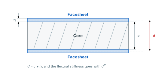
A sandwich beam is a strip of two thin, stiff facesheets bonded to a light core. The faces carry the bending moment as tension and compression, and the core holds them apart and carries the shear. The Sandwich Beam tool is the beam tool with its Sandwich cross-section selected: it runs on the same four supports and three load types as every other section, builds the facesheet stiffness from your own laminate with Classical Lamination Theory, and checks the four ways a sandwich fails locally1.
Two numbers describe the beam. The bending stiffness EI comes from the facesheets alone, and it grows with the square of their separation. The shear stiffness κGA comes from the core alone. A solid laminate beam is so stiff in shear that the shear part of its deflection is often small. A sandwich is the opposite case: with a foam or honeycomb core the shear deflection is often a third of the total or more, and Euler-Bernoulli beam theory misses it entirely. That is why the tool uses Timoshenko beam theory2, which adds the shear part, and reports both parts separately.
A 500 mm sandwich beam on a Divinycell H80 core under a 100 N point load. Of the 2.048 mm deflection, 0.666 mm is core shear.
When to use this tool
Use it for a sandwich strip that spans between supports: a floor beam, a stiffener, a stair tread, a ski or board section, or a coupon in a three-point or cantilever bending test. It answers how far the beam deflects, how much of that is core shear, at what axial load it buckles, and which local failure mode governs.
A sandwich panel loaded over its surface and supported on its edges is a plate problem. Use the sandwich panel tool for that. Both tools read the same facesheet laminate, mirror switch and core, so you can move between them without entering the sandwich again. For a beam made of laminate only, such as a strip, tube, box or I-section, see the beam reference.
Inputs
- Facesheet laminate: a saved laminate or the layup builder. The same laminate is used for both faces. With "Bottom facesheet mirrors the top" on, the bottom face's stacking order is reversed, so the beam stays symmetric about the core mid-plane even when the facesheet laminate itself is unsymmetric.
- Geometry: beam width (b) and beam length (L). The facesheet and core thicknesses set the depth, so there is no height to type in.
- Core: pick one from the core library or type the values. Core thickness (c), ribbon direction (along or across the span), shear modulus in the ribbon direction (Gc,L) and compressive modulus (Ec) are required. Show optional properties opens the transverse shear modulus (Gc,W), the shear strengths (Fsu,L, Fsu,W) and the compressive strength (Fcu). A blank transverse value takes the ribbon value. Save as new core stores what you typed in the core library.
- Loading: Simply Supported (SS-SS), Cantilever (C-F), Fixed-Fixed (C-C) or Fixed-Pinned (C-SS), with a concentrated load (N), a distributed load (N/mm) or an end moment (N·mm). Under a concentrated load, the load pad length (25 mm by default) sets the area the load bears on, which is what the core crushing check reads.
Results
- Response opens with the governing check and its safety factor, the maximum deflection and Pcr. Below that are the bending stiffness EI, the shear stiffness κGA, the bending and shear parts of the deflection and their sum, the maximum moment and shear force with where they sit, the column buckling loads, and the areal weight.
- Checks gives a safety factor per failure mode and highlights the lowest. See the four checks below.
- Diagrams draws shear force, bending moment and deflection along the span. At the picked station it also lists the top and bottom facesheet Nx and the core shear stress τc.
- Resultants sends one facesheet's Nx to the laminate analysis tools. See below.
Key formulas
| Symbol | Name | Formula |
|---|---|---|
| EI | Bending stiffness (facesheets only) | |
| κGA | Shear stiffness (core) | |
| wmax | Maximum deflection | |
| Pcr | Shear-reduced buckling load | |
| Nx | Facesheet membrane force | |
| τc | Core shear stress | |
| σc | Core crushing stress |
- Bending stiffness: taken from the two facesheets alone, about the core mid-plane. The core adds no in-plane stiffness. The coupling of an unmirrored, unsymmetric face pair is condensed out with the reduced bending stiffness, so EI = b·D̃111. The sandwich always uses the reduced D-matrix.
- Shear stiffness: the core carries the shear, so κGA = Gc·b·dx²/c. Here dx is the distance between the stiffness centroids of the two facesheets along the span. A laminated face carries its load closer to its stiffer plies, so dx is shorter when those plies sit next to the core. For symmetric faces dx = c + tf. Gc is the core shear modulus along the span: Gc,L with the ribbon along the span, Gc,W across it (or Gc,L when Gc,W is blank)3.
- Deflection: the bending part grows with the cube of the span and the shear part only linearly, so core shear dominates on short, deep beams and fades on long ones. The coefficients α and β depend on the supports and the load type and are listed on the beam reference. A soft core can make the shear deflection larger than the bending one.
- Buckling: bending and shear act as two springs in series, so the column buckles below the Euler load Pe4. With a soft core Pcr approaches κGA, which is shear crimping. The tool notes when the core's shear governs instead of adding a separate crimping check that could never fail on its own. It works out the buckling load about the core and sideways about the width, and reports the lower one. A narrow sandwich on a stiff core can buckle sideways first, and the tool says so when it does.
The four local checks
A sandwich beam can fail without ever reaching its bending or buckling limit. The core is soft and the faces are thin, so failure usually starts locally, in one of four modes. The Checks tab runs all four and flags the lowest safety factor. Core shear and face wrinkling also say which core direction they used.
The sandwich panel tool runs the same four, with two differences. A plate bends both ways, so it checks core shear in x and in y. And because a plate can buckle under any mix of in-plane loads, it reports general buckling and shear crimping as checks of their own. On a beam both are covered by Pcr on the Response tab.
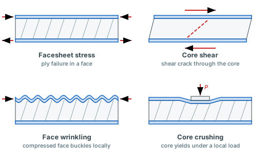
The four local failure modes the Checks tab covers. Schematic, not to scale.
- Facesheet stress: Nx = M/(b·d) on each face at the maximum moment. Each ply takes the strain of the whole beam at its own depth, because a face bonded to the core cannot bend on its own, and is checked with the Maximum Stress criterion.
- Core shear: τc = V/(b·d) at the maximum shear force, against the core shear strength Fsu along the span.
- Face wrinkling: the compressed face buckles into the core over a short wavelength. Its stress at the maximum moment is checked against the Hoff and Mautner wrinkling stress 0.5·(Ef·Ec·Gc)1/35. A stiffer core raises it, so on a light core the face can wrinkle before it reaches its own strength.
- Core crushing: the core under the load, P/(b·pad) for a point load or q/b for a distributed one, against Fcu. An end moment presses on nothing, so it has no crushing check. A short load pad and a soft core both make this check govern sooner.
The Checks tab for the same beam. Face wrinkling governs at a safety factor of 11.40, and the table below names where each check is taken.
Diagrams and resultants
A sagging moment puts the top facesheet in compression and the bottom in tension. A hogging one, at the clamp of a cantilever for example, swaps them. The Diagrams tab draws V, M and w along the span with the support reactions on a free-body sketch, and a vertical cursor marks one station. At that station the tab lists the top and bottom facesheet Nx and the core shear stress τc. The beam reference covers the diagram conventions in full.
The Diagrams tab. The dashed line on the deflection plot is the bending part alone, so the gap to the solid line is core shear.
The Resultants tab sends the chosen facesheet's Nx to the laminate analysis tools, with no Mx and no Qx: the faces take the moment as membrane force and the core takes the shear. Pick a station on the Diagrams tab first and the facesheet force is read there instead of at the maximum moment. With the mirror switch on, sending the bottom facesheet also puts its reversed ply stack in the layup builder, so the ply numbers match the real face. From there, First Ply Failure checks the face with any of the nine criteria, not only Maximum Stress. See Force & Moment Resultants.
Assumptions and limits
- Thin faces. The shear stiffness formula leaves out the faces' own bending, which holds for thin faces. Past tf/c = 0.1 the tool warns that it no longer holds3.
- Linear elastic. No core yielding, debonding or large-deflection effects. A safety factor below 1 says the mode is reached, not what happens after it.
- Bending about one axis. Bending-twisting coupling of the faces (D16, D26) is not modelled.
- Buckling is an upper bound. Pcr is the load for a perfectly straight beam loaded through its centroid. Crookedness and eccentric loading lower it, so apply a design factor.
Author: Rick Schrijver
References
- Zenkert, D. (1995). An Introduction to Sandwich Construction. EMAS Publishing. (Sandwich beam stiffness, local failure modes and wrinkling)
- Gere, J.M. & Timoshenko, S.P. (1997). Mechanics of Materials, 4th ed. PWS Publishing. ISBN: 978-0534934293. (Beam theory with shear deformation, beam deflection tables, and column buckling)
- Allen, H.G. (1969). Analysis and Design of Structural Sandwich Panels. Pergamon Press. (Sandwich beam shear stiffness and the thin-face limit)
- Timoshenko, S.P. & Gere, J.M. (1961). Theory of Elastic Stability, 2nd ed. McGraw-Hill. Section 2.17. (Effect of shearing force on the critical load)
- Hoff, N.J. & Mautner, S.E. (1945). The buckling of sandwich-type panels. Journal of the Aeronautical Sciences, 12(3), 285-297. (Face wrinkling stress)
Frequently Asked Questions
Try it yourself
Size a sandwich beam with your own facesheet laminate and core, and send the facesheet force straight to a ply failure check. It runs in the browser, with a free account and no install.
Create free account