
Thin-Walled Composite Tube and Pressure Vessel Theory
How a thin-walled composite tube carries pressure, axial force, torque, bending and a temperature change: membrane statics on the mean radius, the laminate solve with the wall curvature held at zero, the reaction moments of an unsymmetric wall, and shell buckling with knock-down factors.
Thin-walled composite tube theory treats the wall of a laminated cylinder as a membrane on its mean radius. Whatever the tube carries, the wall sees it as three force resultants Nx, Ny and Nxy in N/mm. The laminate is then solved with its wall curvature held at zero (κ = 0)1, and three shell buckling checks, with their interaction, run on the same resultants2.
This is the method under the Tube & Pressure Vessel tool. The tube and pressure vessel reference covers the inputs, what each result means and a quick-reference table of the formulas. This page derives those formulas: the cuts through the wall that give the resultants, why the wall stays at zero curvature and what that costs an unsymmetric layup, where the thermal terms enter, and how the buckling checks and their knock-down factors are built.
The wall as a membrane on the mean radius
The wall of thickness t has inner radius ri, outer radius ro and mean radius r̄, all in mm:
Every load acts on r̄. This is the thin-wall form, the one behind the boiler formula. Exact equilibrium of the wall would put pi on ri and po on ro, and the two differ by a term of order t/r̄. That difference is the first reason the model asks for a thin wall.
The axes are the laminate axes. x runs along the tube, y around the hoop (the direction θ), and xy is the in-plane shear xθ, so a 0° ply runs along the tube and a 90° ply around it. z points radially outward from the mid-surface of the wall, and ply 1, the top ply with the most positive z, is the outer surface. Internal pressure pi and external pressure po are in MPa and never negative: pi pushes outward, po inward. The axial force F (N) is positive in tension, and the torque T (N·mm) is positive by the right-hand rule about +x. The sign of the bending moment Mb (N·mm) does not matter, for a reason given under bending.
The same tube under internal pressure with two kinds of end. Left, closed: the heads collect the pressure and pass it into the wall as an axial load. Right, open: the pressure loads the wall in the hoop direction only.
Statics: from loads to force resultants
The resultants superpose, so each load can be taken on its own and the results added. Every term comes from cutting the tube and writing equilibrium for the piece that comes away. Two cuts give the pressure terms.
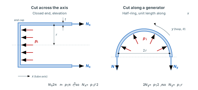
Left, a cut across the axis of a closed-end tube: the pressure on the end cap, piπr̄2, is carried by Nx around the circumference 2πr̄. Right, a half-ring of unit length cut along a generator: the pressure over the projected width 2r̄ is carried by Ny at the two cut edges.
Pressure and axial force, closed and open ends
In a closed-end thin-walled pressure vessel the hoop resultant is twice the axial one, whatever the layup. Cut across the axis, the pressure on a closed end, πr̄2(pi − po), and the axial force F are carried by the wall around its circumference 2πr̄:
Nx is in N/mm, with the pressures in MPa, r̄ in mm and F in N. An open end is a pipe whose end load goes to a support or a sliding seal, the case NASA SP-8007 calls lateral pressure2. Cut along a generator, the pressure on a half-ring of unit length acts over the projected width 2r̄ and is carried by Ny at its two edges:
For an internal pressure p on a closed end, dividing by t gives the membrane stresses in MPa2:
So Ny = 2Nx. Statics alone sets that ratio. The layup only decides how the plies share the 2:1 state, which the worked example below shows.
Torque
A torque T is carried by a uniform shear flow Nxy around the circumference. All of it acts at lever arm r̄, so T = Nxy · 2πr̄ · r̄, and
with Nxy in N/mm and T in N·mm.
Bending and the two sides of the section
A thin circular section has second moment of area I = πr̄3t in mm4. A bending moment Mb gives the axial stress σ = Mbr̄/I at the extreme fibres, and the extreme-fibre axial resultant is σt:
This is the relation Mcr = πr2Nx that NASA SP-8007 uses for a cylinder in bending2. Bending adds ΔNx to the axial resultant on one side of the section and subtracts it on the other:
Ny and Nxy are the same on both sides. The sign of Mb only names which side is which, so the analysis takes |Mb|, checks both sides, and the side with the lower first-ply safety factor governs. With Mb = 0 there is one state and no side.
Worked example: a ±55° vessel under internal pressure
Take an E-glass/epoxy ply with E1 = 41000 MPa, E2 = 10400 MPa, G12 = 4300 MPa and ν12 = 0.28. Lay it up [55/−55/−55/55] in 0.125 mm plies, so t = 0.5 mm, on r̄ = 50 mm with closed ends, and apply pi = 1 MPa. The two cuts give Nx = 25 N/mm and Ny = 50 N/mm, with Nxy = 0. The layup is symmetric, so the zero-curvature solve below gives the ordinary laminate result, and every ply carries the same stresses apart from the sign of the shear:
| Stress | Axes | Value (MPa) |
|---|---|---|
| σx | Tube | 50.0 |
| σy | Tube | 100.0 |
| τxy | Tube | +40.1 in the 55° plies, −40.1 in the −55° plies |
| σ1 | Ply | 121.3 |
| σ2 | Ply | 28.7 |
| τ12 | Ply | +9.8 in the 55° plies, −9.8 in the −55° plies |
Every ply sits at the same angle to the hoop, so σx and σy come out at the average wall stress N/t. The shear stresses of the +55° and −55° plies cancel, which is how Nxy stays zero. In the ply axes the picture is clearer: the fibres carry 121.3 MPa, more than four times the 28.7 MPa across them, and the in-plane shear stays under 10 MPa. A ±55° winding turns the 2:1 membrane state into mostly fibre load.
Why the wall is solved with zero curvature
The laminate law, with the mechanical and thermal resultants summed on the left1, is
N (N/mm) and M (N·mm/mm) are the mechanical resultants, NT and MT the thermal ones at the temperature change ΔT1. ε0 holds the dimensionless mid-surface strains and κ the curvatures in 1/mm. A, B and D are the blocks of the ABD matrix, in N/mm, N and N·mm.
A flat laminate with B ≠ 0 curls when it is loaded in plane, because B couples membrane force into curvature. A closed circular tube cannot curl its wall into a flat-plate curvature. The hoop continuity of the section holds κ = 0, and the membrane strains come from the A block alone:
With κ = 0 the strain ε(z) = ε0 + zκ is the same at every height in the wall1. The top, middle and bottom of a ply carry the same strain and, through σ = Q̄(ε − αΔT), the same stress1. Here σ and the transformed ply stiffness Q̄ are in MPa, the thermal expansion coefficients α in 1/°C and ΔT in °C. Plies at different angles still carry different stresses, because Q̄ and α turn with the ply. Those differences are what the ply check ranks.
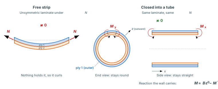
Left, a free strip of an unsymmetric laminate curls under in-plane load. Right, the same laminate closed into a tube: the end view stays round and the side view stays straight, so κ = 0, and the wall carries the reaction moments Mx and My instead. The reactions oppose the curl. Their signs depend on the layup.
The moments are reactions, not loads
The moment rows of the laminate law, at κ = 0, give the mechanical moment the wall has to carry to stay at zero curvature:
M is in N·mm/mm. Nobody applies it. The closed section supplies it, the way a support supplies the reaction on a beam.
A symmetric layup has B = 0 and MT = 0. It needs no reaction, and the zero-curvature solve gives the same strains as the free-plate solve with M = 0. An unsymmetric layup needs a non-zero reaction, and there the two solves differ: the free plate would curl and spread its strain through the thickness, while the tube wall keeps one strain at every height. Put the M above and the same ΔT back into the full ABD solve and it returns κ = 0 and the same ε0, by construction. That makes a quick check if you reproduce the numbers in your own laminate solver.
Worked example: an unsymmetric [0/45/90] tube
Take three T300/5208 plies, each 0.125 mm thick (t = 0.375 mm), with E1 = 181000 MPa, E2 = 10300 MPa, G12 = 7170 MPa and ν12 = 0.28. The 0° ply is on the inner surface, the 45° ply in the middle and the 90° ply outermost, as ply 1. On r̄ = 50 mm with closed ends and pi = 1 MPa, the resultants are the same as for any closed tube of that radius, N = [25, 50, 0] N/mm. The zero-curvature solve gives:
| Quantity | x | y | xy |
|---|---|---|---|
| Mid-surface strain ε0 | 7.697 × 10⁻⁴ | 1.766 × 10⁻³ | −1.784 × 10⁻³ |
| Reaction moment M (N·mm/mm) | −2.062 | 4.732 | 0 |
To stay round and straight, the wall carries a hoop bending moment My of 4.732 N·mm/mm and an axial one, Mx, of −2.062 N·mm/mm. A flat [0/45/90] plate under the same N would take that as curvature instead. The shear strain is not zero either. The single 45° ply leaves the layup unbalanced, so the tube twists under pressure alone, at dφ/dx = γ0xy/r̄ = −3.57 × 10⁻⁵ rad/mm (see twist rate).
Thermal terms
A temperature change ΔT enters through the thermal force resultant NT (N/mm) and moment resultant MT (N·mm/mm)1, built ply by ply as described under hygrothermal effects. Both go into the zero-curvature solve as written above, so ΔT moves the membrane strains and the reaction moment alike.
A symmetric tube has MT = 0. An unsymmetric one does not, and then a temperature change alone needs a reaction. Cool the [0/45/90] tube above by ΔT = −100 °C with no mechanical load and it carries M = [0.835, −0.835, 0] N·mm/mm. Add pi = 1 MPa and the reaction becomes M = [−1.227, 3.896, 0] N·mm/mm. That is the sum of the two cases to rounding, −2.062 + 0.835 and 4.732 − 0.835, because the solve is linear.
A station at height z in the wall, in mm, sits at radius r and moves outward by Δr, both in mm:
ε0y is the total hoop strain of the zero-curvature solve, free thermal expansion included. No radial correction is made to the strain, because that would be a step toward a thick-wall solution.
The buckling checks below read the mechanical resultants only. A free tube's thermal expansion puts no net force on the wall, so ΔT does not enter them.
Twist rate, torsional stiffness and average wall stress
Under pure torque the zero-curvature solve gives γ0xy = (A−1)66Nxy. The twist per unit length is the shear strain over the radius, and the torsional stiffness is GJ = T/(dφ/dx):
dφ/dx is in rad/mm, GJ in N·mm2 and (A−1)66 in mm/N. For a symmetric layup the in-plane shear modulus is Gxy = 1/(t(A−1)66) in MPa, and GJ becomes the familiar 2πr̄3tGxy. The ±55° vessel above has Gxy = 10768 MPa, which gives GJ = 4.23 × 10⁹ N·mm2. The twist rate takes γ0xy from the combined solve. An unbalanced layup, with A16 or A26 non-zero, therefore reports the twist it picks up under pressure alone, as the [0/45/90] tube did.
The average wall stress, in MPa, is each resultant over the thickness, per side when Mb ≠ 0:
Shell buckling with knock-down factors
Three checks run on the mechanical resultants, each against one load: external pressure, axial compression (which also covers the compression side of bending) and torsion. When more than one runs, an interaction check combines them2. Each check needs the length L between the supports, in mm, and each gives the same three numbers. The classical value is the buckling load of a perfect tube. The knock-down factor γ is the empirical factor of NASA SP-8007 that brings it down to what tested tubes carry. The design value is γ times the classical value, and the safety factor of the check is the design value over the applied value. How the results appear in the tool is under Buckling on the tube reference.
Classical buckling of a laminated tube
SP-8007 gives the classical loads of an orthotropic cylinder as the minimum, over the wave numbers, of a determinant built from the wall stiffnesses2. Those closed forms assume a specially orthotropic wall, A16 = A26 = D16 = D26 = 0, and one buckle shape per pair of wave numbers. A laminate with angle plies has D16 and D26 non-zero, and an unbalanced one A16 and A26 as well. Those terms lower the critical loads, skew the buckles and make the torsion load depend on its sign. The one-term form shows none of that. So the analysis solves the same shell equations with the full A and D matrices by the Rayleigh-Ritz method.
The kinematics are Sanders' thin-shell theory3, with x along the axis, y = r̄θ around it, and u, v, w the axial, hoop and outward radial displacements of the mid-surface:
SP-8007 writes its orthotropic equations in Donnell's form, which drops the v/r̄ terms. That is accurate when the tube buckles into many circumferential waves, but it puts the buckling pressure of a long tube at 4D/r̄3 instead of 3D/r̄32, so the Sanders terms stay. External pressure is applied as a follower load that stays normal to the deformed wall. A pressure that kept its direction would also give 4D/r̄3.
Both ends are simply supported: no radial or hoop displacement, free to rotate and free to move axially2. For one circumferential wave number n, u, v and w are sine and cosine series along the tube, each with a cos nθ and a sin nθ part. A16, A26, D16, D26 and Nxy couple those parts. The strain energy of the wall and the work of the prebuckling resultants then give the eigenproblem
K is the stiffness from the A and D energy, KG the geometric stiffness of a unit load pattern, and the critical load factor λ the lowest positive root, minimised over n ≥ 0. The unit patterns are Nx = −1 for axial compression, p = 1 with Ny = −r̄ for external pressure, and Nxy = ±1 for torsion, with the sign of the applied torque. Axial compression is reported as the stress σcr = Nx,cr/t in MPa and torsion as the torque Tcr = 2πr̄2Nxy,cr in N·mm. The buckle shape is the eigenvector: n full waves around the tube, and m, the axial half-wave count that carries the largest share of w.
The solution has no closed form. For an isotropic wall the SP-8007 equations, σcr = 0.605Et/r̄ in axial compression and pcr = 3D/r̄3 for a long tube under external pressure, are asymptotes of it2, so far from their range the Ritz value is the more accurate one. The energy assumes B = 0. An unsymmetric wall gets the same checks on its A and D, and the tool marks them approximate. The ply check does take B.
External pressure
The check runs when the net external pressure, in MPa, is positive:
The knock-down factor is γp = 0.75 at every length, the factor SP-8007 puts on the lateral pressure of orthotropic cylinders2. The safety factor is SFp = γppcr/p.
Axial compression and the bending compression side
When Mb ≠ 0 the axial resultant differs between the two sides of the section. The check takes the peak compressive membrane stress over both sides, in MPa, and runs when it is positive:
One check covers a compressive F, the closed-end axial load of external pressure and the compression side of bending, because SP-8007 treats the peak bending stress of a cylinder by the axial compression procedure2. The safety factor is SFc = γcσcr/σc, with the knock-down factor γc below. Internal pressure on a closed end puts the wall in axial tension, so the check runs only when the other loads overcome it. Internal pressure alone never triggers any of the three checks.
Torsion
The check runs when T ≠ 0. The knock-down factor is γt = 0.67, the factor SP-8007 puts on the torsion load of moderately long orthotropic cylinders2. The safety factor is SFt = γtTcr/|T|. Tcr is solved for the sign of the applied torque, because the coupling terms of angle plies can make a tube buckle at a different torque in each direction.
Combined loads
When two or more checks run, the loads act together. SP-8007 carries the interaction equations of the isotropic cylinder over to orthotropic ones: the load ratios add up to one at buckling2.
Each ratio is the applied value over the design value of its own check, so R = 1/SF for that check. Scaling every load by the same factor scales every ratio by it, so the combined safety factor over the checks that ran is
With one check it equals that check's SF. With two or more it is below every single one. SP-8007 notes that the straight-line sum is conservative for compression with torsion2. SFcomb is the buckling safety factor of the tube, and the load with the largest ratio governs.
Why the knock-down factor is not optional
A knock-down factor scales the classical buckling load of a perfect shell down to what real cylinders reach in test. The classical value is a bifurcation load, and initial geometric imperfections make thin cylinders buckle well below it, so SP-8007 multiplies it by an empirical factor drawn from test data2. For axial compression the factor falls as the wall gets thinner relative to its radius. For a layered orthotropic wall SP-8007 keeps the form of the isotropic factor and replaces the thickness with the geometric mean of the axial and hoop radii of gyration2:
SP-8007 prints φ with the constant 29.8, which is 16 · 121/4 = 29.78 rounded. The analysis keeps the unrounded form above, so an isotropic wall, where D/A = t2/12 and teq = t, gets the isotropic factor exactly. At r̄/teq = 50, φ = √50/16 = 0.442 and γc = 0.678. Double the ratio to 100 and γc drops to 0.581.
The pressure and torsion factors are the √γ = 0.75 and γ3/4 = 0.67 of the isotropic equations, with the correlation factor γ = 0.5625 for pressure2. For very long isotropic cylinders SP-8007 allows more, 0.90 under external pressure and 0.80 in torsion2. The analysis keeps one factor per check at every length. That is conservative on a long tube, and it keeps the design pressure continuous as the buckle shape moves to n = 2 waves.
The factors come from tests on moderately long cylinders. SP-8007 states them above a value of γZ, where Z is the curvature parameter: 2.85 in axial compression, 100 under external pressure and 50 in torsion2. For a laminate the analysis takes Z on the equivalent thickness:
A shorter tube buckles more like a curved plate. It is less sensitive to imperfections and carries more than γ times its classical value, so its design value is conservative, and the tool says so. The classical value holds at every length.
For pure bending SP-8007 gives a separate, higher factor, 1 − 0.731(1 − e−φ)2. Using the axial compression factor on the bending compression side as well is conservative.
What the model leaves out
- Away from the ends. No domed head, end closure, head junction or support is modelled. Near them the wall bends, and the stresses differ from the membrane result.
- No radial stress. The pressures on the inner and outer surface are not applied to the plies as a through-thickness stress.
- Bending moment only. The model takes no transverse shear force from bending.
- No moisture. Only the temperature change enters the hygrothermal terms.
- Linear elastic plies, small strains. Thick walls are out of scope.
- Buckling. Simply supported ends and B = 0. The prebuckling state is membrane only, so internal pressure does not raise the axial buckling load, which is conservative2. A wall whose A or D matrix is not positive definite has no buckling result.
A tube treated as a beam, with deflection under a transverse load and column buckling, is covered by the beam reference. The other structural tools are listed on the structural analysis overview.
Author: Rick Schrijver
References
- Jones, R.M. (1999). Mechanics of Composite Materials, 2nd ed. Taylor & Francis. Chapter 4. ISBN: 978-1560327127. (Eq. 4.13 for the strain through the thickness, Eq. 4.22-4.24 for the laminate stiffnesses, Eq. 4.103-4.107 for the thermal stresses, the thermal force and moment resultants and the laminate law with thermal terms)
- NASA Langley Research Center. (2020). Buckling of Thin-Walled Circular Cylinders. NASA/SP-8007-2020/REV 2, the second revision of NASA SP-8007 (1965, revised 1968). (Section 4.1.1: Eq. 4 for the curvature parameter, Eq. 7-10 for axial compression and its knock-down factor, Eq. 13-14 for bending, Eq. 17-18 for the pressure membrane stresses, Eq. 23-29 for external pressure and its correlation factors, Eq. 33-38 for torsion, Eq. 41-47 for combined loads; Section 4.1.2: Eq. 52-59 for orthotropic axial compression, Eq. 60-63 for the knock-down factors, Eq. 64-66 and the 0.75 factor for lateral pressure, Eq. 69 and the 0.67 factor for torsion, Section 4.1.2.5 for combined loads) ntrs.nasa.gov
- Sanders, J.L., Jr. (1963). Nonlinear theories for thin shells. Quarterly of Applied Mathematics, 21, 21-36. (Strain-displacement relations and rotations of the shell; the cylindrical form is also in Brush, D.O. and Almroth, B.O. (1975), Buckling of Bars, Plates, and Shells, McGraw-Hill, Chapter 5)
Frequently Asked Questions
Try it yourself
Analyse your own laminate tube under pressure, axial force, torque, bending and ΔT at once, with the reaction moments, the ply check on both bending sides and the knock-down factor on every buckling result. It runs in the browser, with a free account and no install.
Create free account